Heat Flux and Temperature Distribution for Heat Sources such as Electrical and Nuclear

Vishwakarma Institute of Technology, 666, Upper Indiranagar, Bibwewadi , Pune, Maharashtra, INDIA - 411 037.
HEAT FLUX:
In physics and engineering, heat
flux or thermal flux, sometimes also referred to as heat flux
density, heat-flow density, or heat flow rate intensity, is a
flow of energy per
unit area per unit time. Its SI units are watts per square-metre (W/m2).
It has both a direction and a magnitude and so it is a vector quantity.
To define the heat flux at a certain point
in space, one takes the limiting case where the size of the surface
becomes infinitesimally small.
The conduction of heat
takes place when the molecules of matter vibrate. Heat energy is transferred
from a higher temperature area to a lower one. This process abides by Fourier’s
law. Fourier’s law is also called the law of thermal conduction equations or
the law of thermal conductivity.
FOURIER’S
LAW
Fourier’s law
states that the negative gradient of temperature and the time rate of heat
transfer is proportional to the area at the right angles of that gradient through
which the heat flows. Fourier’s law is the other name for the law of heat
conduction.
Newton’s law of
cooling and Ohm's Law are discrete and
electrical analogies of Fourier’s law.

Fig 1: Fourier’s Law of Heat Conduction
The
differential form of Fourier’s law can be represented as:
q = - k▽T
where,
·
∇T
is the temperature gradient (K. m-1)
·
k is the conductivity of the materials (W. m-1. K-1)
·
q is the heat flux density vector (W. m-2)
The thermal conductivity (k
or λ) of a substance is nothing but the proportionality constant acquired in
the expression. A body in which energy transfer occurs rapidly by the process
of conduction is considered an excellent thermal conductor. Also, it has a
significant value of k.
To find the solution to
Fourier’s law, the relationship of geometry, temperature difference, and
thermal conductivity of the material should be derived. Joseph Fourier first
introduced this law in the year 1822 and concluded: “The heat flux resulting
from thermal conduction is proportional to the magnitude of the temperature
gradient and opposite to it in sign”.
HEAT FLUX AND TEMPERATURE
DISTRIBUTION IN:
1.
ELECTRIC SOURCE
The
first system is an electric wire of circular cross-section with radius R and
electrical conductivity k, ohm-' cm-'. Through this wire, there is an electric
current with a current density of I amp/cm2. The transmission of an electric current
is an irreversible process, and some electrical energy is converted into heat
(thermal energy). The rate of heat production per unit volume is given by the
expression

The
quantity S, is the heat source resulting from electrical dissipation. We assume
here that the temperature rise in the wire is not so large that the temperature
dependence of either the thermal or electrical conductivity needs to be considered.
The surface of the wire is maintained at temperature To. For the energy balance, we take the system to be a cylindrical shell of thickness Ar and length L. Since
v = 0 in this system, the only contributions to the energy balance are


Fig
2: An electrically heated wire, showing the cylindrical shell over which, the
energy balance is made (6)
This is a first-order
differential equation for the energy flux, and it may be integrated to give

The
integration constant C, must be zero because of the boundary condition that
B.C. 1: at r = 0, q, is not infinite. Hence the final expression for the heat
flux distribution is

This
states that the heat flux increases linearly with r.
Using Fourier's law, we get a parabolic function of the distance r from the wire axis:

Once the temperature and
heat flux distributions are known, various information about the system may be
obtained:
(i) Maximum temperature
rise (at r = 0):

(ii) Average temperature
is:

Thus, the temperature
rise averaged over the cross-section, is half the maximum temperature rise.
(iii) Heat outflow at the
surface (for a length L of wire):
2. NUCLEAR
FUEL RODS
In
Nuclear fuel rods, the energy is released by fission within the fuel rod and is
transferred by heat Conduction to the surface of the fuel and through the
cladding. From the surface of the cladding heat is transferred by convection to
the coolant, which passes from the core to the external heat exchangers in
which steam is generated to operate on a power cycle. A nuclear fuel rod is
used as the source of nuclear energy in a reactor. Most nuclear reactors are
powered by fuel rods that contain two types of uranium: uranium-238 and
uranium-235. The power generation process in a nuclear core is directly
proportional to the fission rate of the fuel and the thermal neutron flux
present. The thermal power produced by a reactor is directly related to the
mass flow rate of the reactor coolant and the temperature difference across the
core. The fuel elements are usually long cylindrical rods or rectangular plates
of uranium (or thorium) enclosed by cladding. The uranium may be in the pure
metallic form, in the form of a compound such as uranium oxide, U02, or in the
form of an alloy with another metal such as aluminium or zirconium. The
desirable properties of fuel, which must be fissionable, are high thermal
conductivity, good corrosion resistance, good mechanical strength at high
temperatures and a high limiting temperature for operation. The numerical
method of solution is used extensively in practical applications to determine
the temperature distribution and heat flow in solids having complicated
geometries, boundary conditions, and temperature-dependent thermal properties.
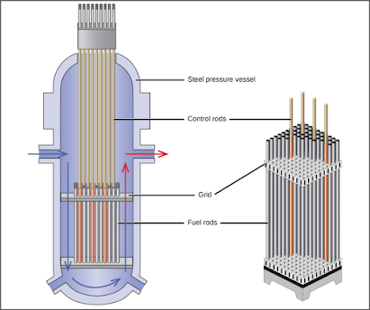
Fig
3: Internal side-view of Nuclear Reactors (4)
An
analysis of the temperature-time behavior introduces problems of unsteady-sate
conduction in fuel elements whose components may be close to or beyond their
melting points and problems of transient heat conduction to a coolant that, in
liquid-cooled reactors, may experience a rapid change of phase. For the sake of
reactor safety and rejuvenation performance, it is important that the selected
coolant is able to remove heat released in the fuel rod because heat
accumulating in the fuel rod causes thermal damage which is dangerous. The maximum,
average, and minimum heat production occurs in the fuel rows adjacent to the first
wall, center of the fissile fuel zone, and adjacent to the tritium breeding
zone, respectively, for various first wall loads and selected coolants (gas,
fiber, natural lithium, and eutectic lithium).
We
consider a spherical nuclear fuel element as shown in below Fig 4. It
consists of a sphere of fissionable material with radius R(F), surrounded by a
spherical shell of aluminum "cladding" with outer radius R(C). Inside
the fuel element, fission fragments are produced that have very high kinetic
energies. Collisions between these fragments and the atoms of the fissionable
material provide the major source of thermal energy in the reactor. Such a
volume source of thermal energy resulting from nuclear fission we call Sn
(cal/cm3. s). This source will not be uniform throughout the sphere of
fissionable material; it will be the smallest at the center of the sphere. For
the purpose of this problem, we assume that the source can be approximated by a
simple parabolic function.

Here Sn, is the volume rate of heat production at the center of the sphere, and b is a dimensionless positive constant. We select as the system a spherical shell of thickness Ar within the sphere of fissionable material. Since the system is not in motion, the energy balance will consist only of heat conduction terms and a source term. The various contributions to the energy balance are:


Fig 4: A spherical nuclear fuel
assembly, showing the temperature distribution within the system. (6)

Substitution
of these terms into the energy balance and integrating it by taking the limits we
get the following two equations:

in
which c1f and C1c are integration constants. These are evaluated by means of
the boundary conditions:
B.C 1: at r = 0,
qr(F) is not finite
B.C 2: at r = R(F),
qr(F) = qr(C)
Evaluation
of the constants then leads to

These
are the heat flux distributions in the fissionable sphere and the
spherical-shell cladding.
Substituting
Fourier’s Law of heat conduction and integrating these equations gives us the
final expressions for the Temperature profile.

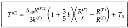
to
find the maximum temperature in the sphere of fissionable material, all we have
to do is set r equal to zero. This is a quantity one might well want to know
when making estimates of thermal deterioration.
Using
these equations one can know (i) how to handle a position-dependent source
term, and (ii) the application of the continuity of temperature and normal heat
flux at the boundary between two solid materials.
GRAPHICAL REPRESENTATION:

Fig 5: Non- Dimensional temperature distribution along the nuclear rods(5)
The governing differential equation for steady-state heat conduction with internal heat generation is considered. The non-uniformity of the internal heat generation with respect to the radial distance has also been taken into account. Here the spherical nuclear fuel element is encountered by symmetry considerations, governing differential equations, and boundary conditions.
The
graphical representation between the non-dimensional temperature and the radial
distance from the center of the nuclear fuel rod unveils that the temperature
is maximum at the center and minimum at the outer diameter. This shows the heat
is transferred from the nuclear fuel rod to the surrounding coolant according
to the second law of thermodynamics. Thus, from the surface of the nuclear fuel
rod, heat is transferred by convection to the coolant, which passes from the
core to the external heat exchangers in which steam is generated to operate on
a power cycle. In this blog, the temperature distribution for the nuclear fuel
rod without cladding has been performed.
REFERENCES
[1] Jian Deng https://doi.org/10.1155/2020/9390645
[2] Fundamentals of Heat and Mass Transfer, 7th Edition. Theodore L. Bergman, Adrienne S. Lavine, Frank P. Incropera. John Wiley & Sons, Incorporated, 2011. ISBN: 9781118137253
[3] Heat and Mass Transfer. Yunus A. Cengel. McGraw-Hill Education, 2011. ISBN: 9780071077866
[4] Osman Ypek, “Fuel Enrichment And Temperature Distribution In Nuclear Fuel Rod In (D-T) Driven Hybrid Reactor System”, Suleyman Demirel Universitesi Muhendislik-Mimarlyk Fakiiltesi, 32260 Isparta, Turkey, 2021.
[5] K.
M. Pandey, Member IACSIT and M. Mahesh, “Determination of Temperature
Distribution in a Cylindrical Nuclear Fuel Rod – a Mathematical Approach”,
International Journal of Innovation, Management and Technology, Vol. 1, No. 5,
December 2010 ISSN: 2010-0248.
[6] Transport Phenomenon, Second Edition, R. Byron Bird, Warren Stewart, Edwin Lightfoot.
Comments
Post a Comment